-
Tel : +86 18148038996
-
Email : zhangwenying@yankong.com
Tel : +86 18148038996
Email : zhangwenying@yankong.com
Item no.:
YKE2608MHPayment:
100% T/T payment before deliveryProduct origin:
Made in ChinaProduct weight:
0.5kgLead Time:
Confirm the PO, normally 7 workdays.YKE2608MH-IO Spontaneous Impulse Stepper Drive
YKE2608MH-IO is a high-performance stepper driver based on a new generation of digital control technology. The control mode of the driver is spontaneous pulse speed control. There are 16 segments of speed can be set by 4 DIP switches, and any speed within the range can be set through the upper computer. Three-way photoelectric isolation digital input, the driver supports motor parameter identification and phase memory functions; Its similar servo control principle, unique circuit design, superior software algorithm processing can make the motor running stably at low speed, and accurate current control technology greatly reduces the motor fever.
Performance:
Application:
YKE2608MH-IO is mainly used for speed controling, loading machine, unloading machine, docking station, logistics transmission, load shifting equipment, electronic equipment
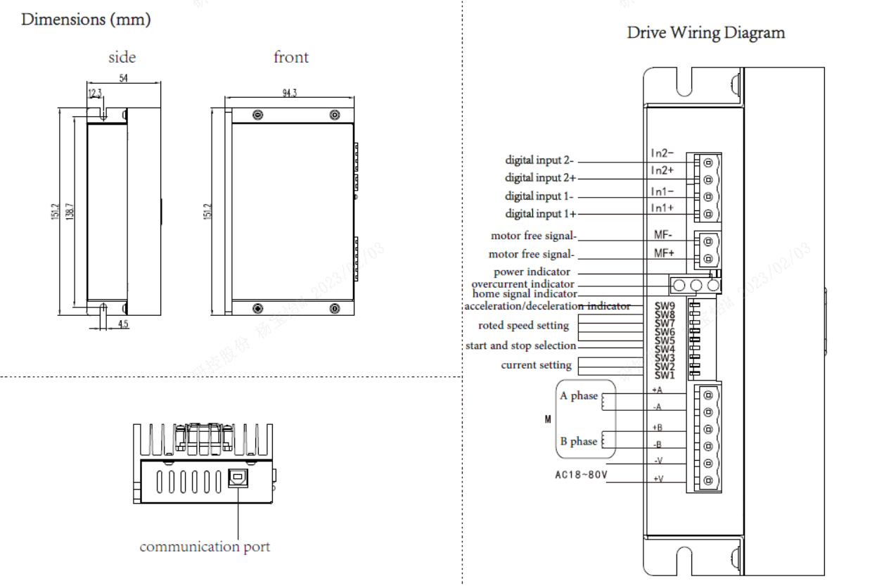
Dimensions:

YKE2608MH-IO Roted Speed Setting:
| The / speed | 0 | 1 | 2 | 3 | 4 | 5 | 6 | 7 | 8 | 9 | 10 | 11 | 12 | 13 | 14 | 15 |
| RPM | 50 | 150 | 250 | 350 | 450 | 550 | 650 | 750 | 850 | 950 | 5 | 10 | 20 | 30 | 40 | 100 |
| SW8 | ON |
ON |
ON |
ON |
ON |
ON |
ON |
ON |
OFF |
OFF |
OFF |
OFF |
OFF |
OFF |
OFF |
OFF |
| SW7 |
ON |
ON |
ON |
ON |
OFF |
OFF |
OFF |
OFF |
ON |
ON |
ON |
ON |
OFF |
OFF |
OFF |
OFF |
| SW6 |
ON |
ON |
OFF |
OFF |
ON |
ON |
OFF |
OFF |
ON |
ON |
OFF |
OFF |
ON |
ON |
OFF |
OFF |
| SW5 |
ON |
OFF |
ON |
OFF |
ON |
OFF |
ON |
OFF |
ON |
OFF |
ON |
OFF |
ON |
OFF |
ON |
OFF |
SW4=OFF Control Mode 2
| lN1 |
lN2 |
statue |
| invalid |
invalid |
locking |
| valid |
invalid |
CW |
|
invalid |
valid | locking |
|
valid |
valid | BW |
lN1
lN2
statue
invalid
invalid
locking
valid
invalid
CW
invalid
valid
BW
valid
valid
locking
YKE2608MH-IO Current Setting:
| RMS | Default(2.00) | 2.57 | 3.14 | 3.71 | 4.28 | 4.86 | 5.43 | 6.00 |
| Peak | Default(2.40) | 3.08 | 3.77 | 4.45 | 5.14 | 5.83 | 6.52 | 7.20 |
| SW3 | ON |
ON |
ON |
ON |
OFF |
OFF |
OFF |
OFF |
| SW2 |
ON |
ON |
OFF |
OFF |
ON |
ON |
OFF |
OFF |
| SW1 |
ON |
OFF |
ON |
OFF |
ON |
OFF |
ON |
OFF |
Terminal Introduction:
|
Symbol |
Function |
Specification |
|||||||
|
PWR |
Power indicator |
When power on, the green indicator lights up. |
|||||||
|
TM |
Work indicator |
Pulse signal indicator, when there is continuous pulse input, the green indicator light flashes, otherwise the green indicator light is always on. |
|||||||
|
O.C |
Fault indicator |
When over current or under voltage, the red indicator lights up. |
|||||||
|
ln1+ |
input signal 1 electro-optical isolation + |
Connect signal power, for +5~+24V, when over +24V the ln1- need to connect current-limiting resistance. |
|||||||
|
ln1- |
input signal 1 electro-optical isolation - |
It requires: low level 0~0.5V, high level 5~24V. |
|||||||
|
ln2+ |
input signal 2 electro-optical isolation + |
Connect signal power, for +5~+24V, when over +24V the ln2- need to connect current-limiting resistance. |
|||||||
|
ln2- |
input signal 2 electro-optical isolation - |
It requires: low level 0~0.5V, high level 5~24V. |
|
||||||
|
MF+ |
Motor free signal +
|
Connect signal power, for +5~+24V, when over +24V the MF- need to connect current-limiting resistance. |
|||||||
|
MF- |
Input signal - |
When it's in low level, cut off the motor current, and the drive stops working |
|||||||
|
-V |
Power supply- |
AC18~80/DC30~110V |
|||||||
|
+V |
Power supply + |
||||||||
|
+A,-A |
Motor connection |
|
|||||||
|
+B,-B |
|||||||||